FAQ’s
Answers to the most frequently asked questions. Check out the FAQ database to find articles about your question.
To reduce internal reflections, MFZ Indoor Dome models use silicone bushings, which require a certain amount of compression to be effective. This necessary compression creates natural friction, which can cause the Pan position to shift slightly during installation. As the top cover is secured with a rotational method, friction between the silicone on the dome cover can cause the Pan position to shift.
- During the process of combining the dome and the body, the Pan position may change. Therefore, anticipate this change, adjust the Pan position accordingly, and then proceed with the fastening.
- For indoor dome cameras, including MFZ Indoor Dome cameras, the upper bubble can still rotate even after fastening the lower part of the bubble. After securing the lower part, rotate the upper part to adjust the PAN direction as desired. Be careful not to leave fingerprints or foreign objects on the bubble in front of the lens.
1. After logging in, click on ‘My Profile’ in the upper right corner.

2. Click on ‘Modify’ to enter the settings page.

3. Click on ‘Do you agree to receive email?’ to start receiving notification emails.

In the case of its IP Camera, you can check the Video/Audio output at the same time by entering the following RTSP command into the VNC player.
E.g.) rtsp://{ip address}:554/onvif/media?profile=Profile1
– If you want to test audio only, you can use the following RTSP command (H.265 Camera Only)
E.g.) rtsp://{ip address}:554/trackID=90
– If the audio is not heard in VNC, etc., check the Audio Track or Output device information setting in the Audio menu.
In the current local environment of one computer
Person Match Service and Video Analytics Service cannot be working together.
Current local computer IP: 172.17.27.17
Current INEX(ISS) Version: Expert 4.0.4
Install the current Video Analytics Service and Person Match Service on the same computer
It is possible to install it, but it is confirmed that it does not work properly as shown in the following figure. The reason why the service cannot be loaded properly in Admin is that it does not work properly as confirmed by Service Manager.
Person If you want to use both Match Service and Video Analytics Service together, you can install the service separately on different computers, and then connect it to the same network by looking at the adminip.
※For reference, if Person Match Service is being used on one computer, Person Match Service cannot be used on another computer.
Test Sample Method
1. Prior to making sure NVR is on the same network as my pc
2. Webhook site access -> check red box (pictured below)
3. Make sure to write your own unique number in the red box when setting up NVR -> Notification -> HTTP settings (see other pictures)
4. NVR ->Custom Value -> Set as shown below (sample)
5. For example, if you want to capture an event for a particular situation with your camera and receive the result as HTTP JSON, you can set it as follows
6. 6. EVENT -> Motion -> zone, setup, condition setup -> Actions -> notify -> HTTP click -> ok


We noticed that his IDLA does not offer the DC-T6233HRXL as available for IDLA service.
I checked our IDLA and have the same issue. We have DC-D6233HRXL connected but it doesnt appear in the IDLA availability list.
A :
DC-T6233HRXL is VA Edge camera which support Line crossing, Loitering, Object detection.
IDLA does not support IDIS VA Edge camera.
If you want to use that camera o IDLA service,
It needs to change DC-T6233HRXL to DC-T3233HRXL.
it can be changed by firmware upgrade.
Beide functies zijn gebeurtenissen die optreden wanneer het scherm door iemand wordt bedekt.
Het verschil tussen de twee functies is dat Video Blind geen Video Blind off-bericht genereert totdat de schermbedekking is opgelost,
Tempering zorgt voor aan- en uitzetten wanneer schermbedekkingen optreden, ongeacht of de schermbedekkingen zijn opgelost.
At Customer PJT, which was built in 2018,
I’m trying to build additional ISS Backup service, and I have a license inquiry.
The customer will probably install each backup service under admin.
In this case,
1. Do I just follow the 1st admin backup device below for the license?
2. Or should I buy a backup device channel as well?
A:
You can follow the Backup Device on the system on which the backup service will operate.
When the Backup service is registered with Admin, Admin,
When the Backup service is registered with Federation, it is Federation.
Yes, the camera’s own SD recording status is not displayed on the OSD.
The recording status OSD is displayed by referring to the recording status information sent by the device, but the camera does not deliver the information.
Regards to DR-6500,
From the v8.1.0, below features support on special version, we called SI Firmware.
Please contact IDIS support team, we will help you.
support@bnl.idisglobal.com
I have confirmed and shared the new TR-2516 constraints.
Issue: Provision AHD, Hik TVI 4MP/5MP camera shown only 1280×1440 when connected to TR-2516.
– Maximum resolution possible when the same camera is connected to the TR-1508.
The issue is limited to 4M Half/5M Half mode due to TR-2516 chipset performance limit.
TR-150x/TR-2504/TR-2508/TR-45xx have no chipset performance limitations.
Example)
4M30 : (Recognized as 4M Half) 1280×1440 15ips
4M15 : 2560×1440 7ips
5M20 : (recognized as 5M Half) 1280×1920 10ips
5M12 : 2560×1920 7ips
If IPS is set lower in AHD, TVI camera settings, TR-2516 will enable resolution rather than half mode.
Third-party AHD (Provision) and TVI (Hik) cameras found on Onsite do not have 4M15ips and 5M12ips options.
In this case, TR-2516 does not enable maximum camera resolution.
– 5M 12.5ips is supported for IDIS TVI 5M models, so maximum resolution is available.
Other models, TR-15xx, TR-2504/2508, and TR-4508/4516, do not have this constraint, so this is not a problem.
DR-1000 series is a small form factor product and supports only IDIS cameras. Non-Onvif third-party cameras are not supported.
An additional IP camera can be connected to the LAN/POE OUT PORT of DV-1304-A, and POE is provided.
However, it is necessary to connect a DC 48V Adapter to use it.
Refer to the following for details on the power supply.
0. 0. DV-1304-A can be powered w/ two power sources
1. 1. when powered via PoE (802.3at class 4 25W)
=> when powered w/ PoE, only the DV-1304-A works and it will draw max 25W
=> the PoE power draw in the NVR is showing total. please ignore the per channel power consumption
2. 2. when powered by DC 48V@1A on the DC power in terminal (48VDC@0.8A = 38.4W)
=> the PoE Out on DV-1304-A is only powered when DC power is used
=> it will draw max 1A and use about 38.4W for both DV-1304-A and PoE out
=> it can supply 48V@0.35A max on the port PSE (16.8W), so it’s about, 802.3af class3 (15.4 W max)
If you have backed-up ISS settings (*.iexp), importing them will enable existing data to be recognized.
If you do not have an existing setup backup, the ISS Setup>Recording Service>Storage>Import function can retrieve the existing recording data and retrieve it as a deleted device.
Q :
We found a possible issue with the PoE on this device. The problem happens when the IR lights come on in the cameras. There seems to be a PoE overload so one camera loses power.
When we turn off the IR light on the bullet camera, then the Fisheye camera that turned off comes on again.
The below is the PoE status with the bullet IR turned off.
![]()
This is with the Bullet IR turned On
![]()
A.
From products produced since June 2022, (PD69104B1)
The PSE controller has been changed and has the following restrictions.
The corresponding NVR is determined by the following circumstances.
1. Current: Port is managed by Group, power is limited if it exceeds 37W per Group.
– – Gruop0 : CAM1 ~ 5
– – Group1 : CAM5 ~ 8
All cameras are currently connected to Group0.

To solve the problem,
Connecting the camera to Group0 and Group1 seperately would solve the problem
Officially, we can say 1 IPC linked from the camera.
Power
PoE, IEEE 802.3at(Class 4), 25.5W
(DC OUT : 42.5-57V=, 0.3A MAX)
DC OUT is extended port.
42.5V x 0.3A = 12.75W (min)
57V x 0.3A = 17.1W(Max)
So, at least DC OUT (Extender port) can provide 12.75W~17.1W
Basically, DC-D4517 series consumes about 7W.
12.75W – 7W = 5.75W. thus it’s not enough to support additional third camera.
Q : What is the maximum distance I can reach with the PoE extender?
A. it’s 100 meter. It’s same as ethernet interface. But you know, you have to consider margin for installation.
I think most of installer takes about 70meter for the safe.
You need to refer to the calculator and find which DA-ES1104 type compatible with DR-8532D
– when you click “External Storage Compatibility List” > you can see the DA-ES1104B type compatible with DR-8532D
– DA-ES1104B support upto 12TB

Make sure the time is synchronized on both devices and check “Using Onvif Option” if it’s available.
Yes. You can use the camera but please note that the support will be limited for umcompatible cameras.
[NVR] SMTP 503 Error
This error often reported an email account is provided by Google Gmail.
Go to Google account > Personal Setting > Untick Unknown Source Checkbox.
A. In general, setup should be done 3 sides to use a network keyboard.
1. Keyboard local side : Device setting page from IDIS Discovery Tool : Register Server
2. ISS setup side : Register a network keyboard at Device tab.
3. ISS Client setup side : Turn on “Use Network Keyboard” option from Preferences.
A. The error message means that the device sessions are fully occupied.
Try to remove some sessions or close connections from Clients.
A. CGNAT means Carrier-grade NAT and this is used a solution for IP address exhaustion.
Lots of Internet Service Providers(ISP) implementing this device in 3 network infrastructure.
This could impact on the stability of FEN connection on your client devices.
In this case, call local ISP and ask them opt-out from CGNAT Pool. Implementing a FEN relay service also can be a solution for this issue.
A. INK1200 network keyboard can control IDIS Camera’s Wiper.
* Commands :
– Input keys when a camera pane is selected.
– Wiper ON : Press 1 Press AUX (Wiper will move 3 times)
– Wiper OFF : Press Press AUX + Shift(together) (Wiper will stop moving)
A. Yes. it is possible from IDIS Center version over 6.1.0.
A. Prepare a PC and connect HDMI encoder. Run the video on the PC and register the HDMI encoder to NVR or ISS.
No, Face Detection is available on the DV-1304-A.
A. DV-1304 has People Counting(Exceed the Occupancy Limit), Queue Monitoring(Queue Congestion), Heatmap, Mask Rule Violation and Social Distancing Violation Features.
DV-1304-A has Object Detection, Intrusion, Loitering, Line Crossing and Face Detection Features.
Q. If the mobile phone is in the WIFI, user can use Auto Login option.
However, it seems that auto log-in is not working when the IDIS Mobile Camera App comes up from the Background.
A. if the App comes up within 10 seconds after app goes background, the screen comes out as it is.
After 10 seconds, it logs out.
After that, if user again runs the Mobile App, it will be auto log-in
A. Initialization takes about 30 seconds to setup.
In addtion, IDIS tells the build time is 200GB/hour regardless of mode.
It is the worst case, so it’s actually faster than this.
A. Ja. Wij raden aan om HDD’s met dezelfde capaciteit te gebruiken in 1 eSATA-opslag.
Zelfs als de HDD’s verschillende capaciteiten hebben, werkt eSATA. Als de gebruiker echter RAID instelt, wordt de totale capaciteit berekend op basis van een lage capaciteit.
Dit betekent dat de gebruiker niet zoveel kan gebruiken als het verschil in capaciteit tussen twee HDD’s.
Bovendien verhoogt het gebruik van HDD’s met verschillende formaten het aantal probleemgevallen, waardoor het moeilijk wordt om technische ondersteuning te bieden.
A. For example, assuming that the height of detected object as human is 1.7m.
The distance by level is as follows.
Level 1 : 0.7m
Level 2 : 1.4m
Level 3 : 2m
Level 4 : 2.7m
Level 5 : 3.4m
A. User can change the IP address if the DV-1304 have never registered to the NVR before.
If user wants to change it, please do factory reset and then change the IP address.
To support DIP 1.0 cameras, here are supported functions in INIT
1. Setup : IP address setup
2. Reset : Soft, Factory
3. Management : Upgrade, System log
A. There is no specific limitation, Our LAB tested registration upto 4000 NVRs.
A. The IDIS Center manages device names if the Device Name Sync is unticked.
In this case, even if user changes the device name, IDIS Center shows the existing device name.
“Setup > Double Click the Device > Edit Device > Tick/Untick Device Name Sync”
A. The ADC key value entered by OSD button is read by VD Sync.
In addition, to prevent malfunction due to noise, it is operated when the input value is maintained at least 2 frames.
Thus, 12.5fps has a long interval VD Sync so, it works relateively slowly,
A. The debug information is extracted based on the time of extraction.
After first export, based on the existing file, only the new debug is extracted.
Therefore, if there is no new information, it will have same size. On the contrary, if there is new, it extract new information only.
A. It is used for seamless communication even in low bandwith network.
However,, if “Device Low Bandwidth Communication” is enabled, it is not effective in the normal network because it trys handshake communication between the device and client.
A. No. DV-1304(-A) has compatible with only IDIS Camera, not Onvif Camera.
A. Intelligent TLS is a level similar to TLS Very High level (Exclude Multimedia SSL).
General Exclude Multimedia SSL is used in Windows, and since it requires significant additional performance, ISS performance may be greatly reduced.
To solve this, SSL/TLS was applied according to our protocol to improve processing speed so as not to affect performance.
A.
1. Online Mode : Initial access to the License Server once, then no need to connect it. After Verificatioin the License Key, internet is not required.
2. Offline Mode : Input the key without Internet.
3. Cloud Mode : It has to keep opening internet access, because Admin service keeps connection to the license server every day. limited time is 24 hours. If the network is disconnected and flows without recover it, ISS services goes out (Status : Demo Expired) if the ISS service restarts.
A. Please refer to the image.
Other bullet camera also has factory reset button inside.

A. In general set up should be done on 3 sides to use a network keyboard.
1. Keyboard local side: Register server
2. ISS setup side: Register a network keyboard at Device tab
3. ISS Client setup side: Turn on ‘Use Network Keyboard’ option
A. CGNAT means Carrier-grade NAT and this is used a solution for IP address exhaustion. Lots of Internet Service Providers(ISP) implementing this device in there network infrastructure.
This could impact on the stability of FEN connection on your client devices. In this case, call local ISP and ask them opt-out from CGNAT pool.
A. FEN relay server is a server that relays data from IDIS device to client software.
This often can overcome a limitation caused by complex network infrastructure.
However, additional configuration and decision have to made by customers.
A, Go to Menu > Preference > System
Untick “Disabled display scaling on high DPI settings”.
A. Go to Menu > View > Recorder Storage Monitor.
In that menu, all storages connected to recorders will be displayed.

A. Use IDIS HDMI Encoder such as HE-1101 and DP-HE1201.
ISS(IDLA analysis) – HDMI Encoder – Analog Recorder – HD-TVI camera.
Register HDMI encoder on ISS and then select it in the VA service > IDLA.
A. There is no specific limitation numbers of Log-in List.
A. IPv4, IPv6, RTP/RTSP/TCP, RTP/RTSP/HTTP/TCP, RTP/UDP RTSP/TCP, HTTP, HTTPS, SMTP, FEN, mDNS
A. Yes, ISS supports SAN.
A. The MiniBankPlayer.exe is a SelfPlayer that plays recorded videos of old IDIS Recorders.
It is a previous software of the current Clip Player.
It is not a software that has viruses or affects security.
A. The rear PoE group MAX specifications for DR-2308/2316 products are as follows.
#1. Port 1~4 : total 37W
#2. Port 5~8 : total 37W
The total port is 74W and the rated usage is 50W.
If over 50W is used, the 48V adapter life is not guaranteed.
A. There won’t be problem in the snow-covered image.
However, if there is a snowman or a snowy, it can cause misrecognized problems.
A. No, IDIS Mobile Plus doesn’t support Playback Audio yet.
A. Because the status is notified to the FEN server every 3 minutes, the connection is maintained.
A. When installing and operating ISS on a cloud server such as Azure, the basic h/w information of the server could be changed, [Cloud authentication method] must be used for the license registration method.
If customer uses the license type, ISS is designed to accept and update the authentication method from the cloud server from time to time to maintain License authentication.
To do this, the server must always be connected to the Internet.
A. Various meanings are given to the colors of the IDIS record bar.
Please refer to the table below

A: IDIS NVR stores 10000 lines of log.
A. Queue Monitoring is literally a function that measures how long people wait in line in places with a lot of waiting, such as restaurants and super market.
There is also a Mid/High Congestion option, so if the queue gets a bit long, It can alert the manager and he can respond immediately to the scene.
Also, through the VA Dashboard, you can monitor the day/week/month/year unit queue data and check the congestion level by period.
A : Yes, they can use the same login information, if one channel is just created on ISS, one of the apps is able to be registered,
But another will be failed to register, because the channel will be full.
In this case, the one channel for app2 needs to be created.
A : first of all, It requires IDIS Mobile camera channel on ISS in advance, and then the Mobile camera accesses Admin service.
Then, the image traffic flows to Mobile Camera => ISS Mobile service => ISS Streaming service => Live view or ISS Recording service
A : for this, Admin, Streaming, Monitoring, Mobile service must be installed. And Recording service is also required for the recording.
Q. The DV-1304 is not directly connected to the NVR, it is connected to the switch.
A. By any chance, what is the PoE power consumption of the switch?
If the switch supports 802.3af, it may not provide enough power and cause malfunctions such as restart. Please check whether the device supports 802.3at.
A.
In the past, you could select which interface (LAN, RS232, 485, etc.) to use in the Text-In setting within the Event, but in the recently released new firmware, this part has been organized and functionally separated.
Changes
– Add Device Type/Port settings to be used in TextIn in advance in “DEVICE->Connector” as shown below, and then
Changed the way to select the Connector to use in “Event->Text-In”.

A : RAID should not be used in DV-3100, and only one HDD is allowed to store DB.
Otherwise, unexpected problems may occur.
A.
This phenomenon occurs occasionally in devices using Windows operating system, but there are cases where the set resolution is reflected only in the UI.
In this case,
Instead of changing in “Display Settings” that appears when right-clicking on the desktop, try changing the resolution in the graphics card settings. (Example: “NVIDIA Control Panel”, “Intel R Graphics Settings”)
When changing, please change to 30Hz for UHD (3840×2160) and 60Hz for FHD (1920×1080).
Detailed description:
When changing in window display settings: The actual video signal output is UHD, but only the UI is changed to FHD and output
When changing in the graphic card settings: the actual video signal is changed from UHD to FHD
A. Up to 1000 can be stored in IDIS Solution Suite Client, after 1000, license plate images are overwritten from the oldest.
Please visit “Technology Partners” page
https://www.idisglobal.com/index/techpartner
A: Go to IDIS Solution Suite Setup -> Device -> Select Device -> Open Tree menu -> Select Camera -> Edit Device -> Turn on Associated Audio Channel
The device must support audio.

A: Yes, the 2 camera models can record audio, and listen to audio from live monitoring.
Q. When I try to register the Mobile camera app to the ISS, it fails. Why?
A.
IDIS Mobile camera app is classified as 3rd party device license, not IDIS Device license according to company regulations.
Therefore, 3rd party device number must be added to the license as much as the number of mobile camera apps to be registered.
Q.
Our customer has to record with ISS in the cloud. The cloud recording servers are located in the Pacific time zone but the local stores / cameras are located all over the US in 4 different time zones.
How will this affect the event recording and searching?
For example, an event occurs in New York at 8am – which is 5am in Pacific time. Now when the investigator comes to work in California at 9am Pacific, he searches for the event which occurred at 8am. If I am correct, that will be actually searching for an event at 11am Eastern?
A.
The Time follows Admin service’s time.
So, if the camera is in New York at 8am, and Recorder Server is in Pacific zone at 5am.
the time goes to depending on the where Admin service(ADM) is at.
if the ADM is in Pacific zone, the footage time of camera records as 5am.
if the ADM is in New York, the footage time of camera records as 8am.
Because the time follows ADM service time, so it may need to adjust the time setting on ADM server if you need.
1. IDIS Center, ISS Client:
The maximum number of monitors per PC is not limited
-> It is determined by the number of monitors in the display settings of the OS. (can be increased as many as the number of graphics cards can support)
2. ISS Video Wall Agent : Supports up to 6 monitors
Only for ISS license registered in Online mode,
If the WAN network is disconnected, the license is maintained for 14 days.
After that, if the Admin service is restarted, it will change to “Demo Expired”, so be careful.
Q : I am currently using IDLA 16ch x IP camera. Additionally, I am trying to build a Person Match,
I would like to know if I need to purchase an additional VA License or if I can currently use Person Match as much as 16ch.
A : The ISS VA license includes the number of Person Match licenses as much as the number of VA licenses.
That is, if you have 16ch x VA License, it is equivalent to having the following license.(regardless of pre-processed mode and recorded footage mode)
– IDLA service X 16ch
– Person Match x 16ch
Yes, Person Match search is only possible for one user, that is, one session.
When the Person Match tab is closed, the session is terminated and immediately available to other users.
If the user does not take any additional actions for 30 minutes after the Person Match search is finished,
Session is automatically terminated and can be used by other users after that.
This is because in the TR-4216 products, a policy to apply weights to bitrate to reinforce image quality at low tips has been applied.
Yes. It is recorded as ‘Fan Error(CPU)’.
The event logs are stored in HDD, so there is no number limit.
However, if the recording data is overwritten due to HDD capacity, also the event logs for the overwritten recording are deleted.
Yes. When it inserted in IDIS Network Camera, it will be automatically formated in our filesystem.
Yes
IDIS Center for iHDP is a S/W to access the HDD of NVR frome a PC to enable playback Therefore, Complete data has to be stored in a single HDD.(RAID 1+0, 5, 6 store different parts of data in each HDDs)
Use RAID HDD playback through remote access from iRAS to NVR.
There is no priority, and if either works, it is synchronized immediately.
Both have same capacity (Up to 256GB)
If ‘Anti-flicker On/Off’ doesn’t solve it, you should find a value that improves in the following way.
Go to ‘Anti-flicker Off’ -> ‘Exposure Control’ -> ‘Manual’
And, Set Shuter speed Min and Max value the same and manually find a value that improves flicker by setting the value to a multiple of 60.
(ex. 1/60, 1/120
No, there is no way yet.
Without RTC battery, Camera returns to 1/1/1971 when rebooting.
PoE (IEEE 802.3at class 4) supported 8 ports, 50W
There are group limitations :
Port 1 ~ 4 : 37W
Port 5 ~ 8 : 37W
The guaranteed time is 1 week.
For 8-ports model, it supports upto 8 IEEE 802.3af and upto 2 IEEE 802.3at.
For 16-ports model, it supports upto 16 IEEE 802.3af and upto 4 IEEE 802.3at.
Frequent Power On/Off operations are difficult to recommend
Up to 16
We provide ‘AE Target Gain’ function as ‘Auto Gain Control’
You can set ‘Camera Setup -> Video Tab -> Exposure -> AE Target Gain’
Users can generate the “Email” and “Callback” event when the SD card is in/out
“Camera Setup ➔ Event ➔ System Event ➔ Disk In/Out”
Since Person Match service uses recording(= Playback session) serssion of Recorder.
so, In ISS recording service, upto 10 session can be available,
In NVR side, upto 2 session is available.
however, If a Client is using the recording session of NVR, 1 Person match service is available.
No. Depending on your situation, you may want to Detach > Install on a different server. / However, since it is a cost issue, I would like to recommend installing it in the PM server as much as possible.
No, Recorded Footage mode does not use MariaDB
Yes, if Person Match is not set, IDLA is not stored in MariaDB.
Both services are using the same VA Engine(called IDLE), there is no difference in recognition rate, and the specification is the same as upto 50 object simultaneous monitoring. However, note that the optimal performance is upto 16ch.
Person Match Service Licenses
The Video Analytics (IDLA) and Person Match Services use and share the ISS VA license. If you are already using the IDLA, the PM service is provided as a free upgrade.
Even when adding multiple PM service in a single Admin Service, it is used as the total number of channels purchased.
As PM service is in Federation, the IDLA license for PM service should be included to Federation license,
As PM service is in Admin, the IDLA license for PM service should be included to Admin license.
Person Match Service at Federation service
Person Match is also available in Federation service.
As mentioned above, when performing PM search, data traffic increases instantaneously because the PM service directly accesses multiple recorders or recording services to retrieve and analyze data.
In other words, it should be used in a space with sufficient bandwidth of the network. In other words, if you need to install PM service in the location where Federation is installed, it is necessary to review beforehand whether the network bandwidth and latency are sufficient.
However, when building a system, you need to understand the operation method and data flow in order to build it correctly.
Case1: When FED (Federation) has a PM license
Case2: When ADM registered in FED has a PM license
Case1: When PM service is registered in FED
PM search can be done at ISS FED CLIENT. ISS FED CLIENT can perform PM search for all cameras.
However, if the network bandwidth between the recorder (ADM) and PM (FED) is insufficient due to the system structure, the search speed may be quite reduced, so please be careful.
For example, if the bandwidth between a bank’s ATM and the monitoring center is very limited, it can be a problem when performing PM search.
In this case, Case2: When ADM registered in FED has a PM license.
In this case, Federation should have IDLA(PM) license.
As many as IDLA(PM) license applied, user can search the number of channel(IP camera)
Case2 : When ADM registered in FED has a PM license
As above, if the bandwidth between ATM and monitoring center is low, Case 1 is not appropriate.
In this case, while building PM service on the ATM side, it is built on site to secure sufficient bandwidth for VA.
Note: In this case, PM search cannot be run for the camera of ATM2.
For PM service, PM serivce must be installed in the admin service.
In this case, Federation dose not need to have IDLA license, but Admin license should have it.
(With above diagram, ATM2 site cannot use Person match service, because there is no Person match service installed)
Q: I am monitoring real-time video over 144 channels by connecting 4 monitors with Intel i7 + Quadro P1000 (GPU) configuration.
By the way, up to the 2nd monitor is normal, but from the 3rd monitor, the video is cut off. Why is that and what should be done?
A:
1) Intel i7 CPU
+) i7 CPU also has a grade, but the general i7 has 4 cores (Quad Core).
From a multimedia data processing point of view, this is an intermediate specification.
+) CPU selection is very important in real-time monitoring operation of more than 144 channels (cameras) in a configuration of 4 monitors.
2) Quadro P1000 GPU
+) The P1000 has the advantages of low power and easy multi-monitor configuration, but it is a low-spec GPU.
+) It is a better GPU than the GPU used in development, so it is difficult to conclude that the current information is the cause of the issue.
** Issue identification
+) If the CPU occupancy exceeds 90% and the phenomenon is reproduced, there is a high probability that it is a CPU issue.
+) CPU usage is less than 85%, but if the phenomenon is reproduced, there is a high probability that it is a GPU or MEM (out of memory) issue.
In addition to +), it is necessary to review the overall operating environment (OS / CPU / MEM / GPU / Device Driver / Etc)
** check item
1) Check camera stream settings and dynamic multi-stream control configuration
2) Check the camera stream encoding codec (H.264)
+) H.264 has much less decoding load than H.265.
+) It is recommended to use the H.264 codec for the stream used for multi-channel monitoring.
3) Activating camera settings intelligent codec
4) Default value is recommended for Client S/W setting (Preference – Video Enhancement)
+) In a low-end GPU environment, it is necessary to check the phenomenon depending on whether High-Quality Downscaling is used.
This mode is almost the opposite of ‘Pre-Processed Footage mode’ in operation.
When PM service is executed, it directly accesses the recorder or Recording service, accesses the recorded data and performs analysis (IDLA).
Also, this mode can do PM search with any camera (the biggest difference from Pre-processed Footage mode)
Advantages :
‘Pre-Processed Footage mode’ costs a lot when building a service, but Recorded Footage mode doesn’t require IDLA VA service and MariaDB for pre-processed VA metadata like the above configuration. (In other words, the construction cost is lower than the Pre-Processed Footage mode.)
So, if the cost of H/W is burdened, you can use this mode.
Person Match / Pre-Processed Footage
Among those two modes, the one with the fastest search speed is Pre-Processed Footage. This function classifies objects in advance (pre-processing), stores them in a separate database server (MariaDB), and searches through PM service if necessary. It has the advantage of faster search speed compared to Recorded Footage mode.
Also, when PM service is running, it is good because the search session resource is not consumed because it connects to MariaDB instead of directly connecting to the recorder. Devices like NVR only have two search sessions, so if there are many users who use ISS playback at the same time, the search session of NVR full may occur and PM search of NVR may not be possible.
In summary, the advantages of Pre-Processed Footage are:
– Fast search speed
– It is suitable for the system environment that has the restriction of search session such as NVR or TVR.
However, this service also has its weakness.
– Increased cost: IDLA Server and MariaDB storage capacity are required because pre-processing is required using IDLA and DB is stored by building MariaDB. That incurs additional costs.
+ However, if you are a user who already uses IDLA, there is no cost issue. (You only need to add as much storage capacity as MariaDB)
– Restriction that only cameras analyzed through IDLA can be used:
+ Data analyzed in advance through IDLA are stored in MariaDB, and this data is used by PM service, so there is a limitation that only cameras analyzed through IDLA can be used. / There is a restriction that other cameras cannot use PM service.
+ But you have to think about this, there are some cameras all people must pass through. For example, building entrances, checkout counters.
Therefore, it is necessary to recognize the pros and cons of the function and introduce the most appropriate service to the customer.
There is an IDIS Deep Learning Engine called IDLE, and using it, we are providing an IDIS VA(Video Analytics) technology called IDLA.
This time, we would like to introduce another VA technology called Person Match, which is a type of IDLA.
IDIS Person Match (hereinafter, PM) is a function that VA directly finds the person you are looking for.
If you find the person you are looking for in the video and run PM search, you can easily find out when and where the person is.
In the days without PM technology, security officers or police officers had to manually search through numerous CCTV footage for a very long time to solve a case. But now they don’t have to.
This PM is a service belonging to ISS VA (IDLA), so IDLA license is used.
This also means that customers who already use IDLA can use PM service for free.
This IDIS PM service has two main modes.
– Person Match / Pre-Processed Footage
– Person Match / Recorded Footage mode
VA Dashboard is a graph that shows the trend of problem occurrences, which means it does not represent an exact value of the events.
In other words, rather than displaying the total number of events, events that have occurred during one minute are counted as Violation 1.
If all 23 mask violation events occur within 1 minute, VA Dashboard counts them as 1.
A customer can misunderstanding about the current interval time of 1 minute has been received, and we intend to reduce it to 10 seconds.
Then, a value similar to the customer’s intended result may be displayed.
I was able to change the camera IP settings in DirectIP 1.0 NVR.
However, please note that the IP setting function in the tool is not supported after moving to the DirectIP2.0 generation.
Does DC-S6283/3583/3883 meet IK10? The material of the instrument is plastic, how does it meet IK10?
The reason why the customer guessed that it would be difficult to meet IK10 after checking the exterior material
It is likely that the judgment was made by looking at the plastic exterior parts.
The exterior plastic parts used in this product use a PC mixed material that can easily absorb shock, and the basic thickness of 3T is applied to prevent damage to ensure safety.
ISS has a Backup service module, you can use this service and back it up and store the NVR’s HDD separately as replacement HDDs.
– How to configure of ISS
1. Uncheck ‘Overwrite backup data when the disk is full’
When assign HDD storage on Backup service, ‘Overwrite backup data when the disk is full’ should be unchecked so that Overwrite feature stop.
2. Check ‘Notification of Disk Almost Full’ as 90%
3. When setting the backup for the first time, it is recommended to set “first / summary backup or event backup”.
This is due to the network throughput performance and h/w performance limitations of the Recorder.
4. If the HDD is full and needs replacement, as shown in the picture below,
Make a note of the last recorded date/time before replacement, and when you connect a new HDD and reconfigure backup, you can start recording from the time you wrote the note.
5. There is currently no function in ISS that gives an alarm when starting a new HDD recording.
– how it works
+ please refer to Page. 263 on ISS v3.5 or higher version manual.
+ the traffic flows as below :
Camera(device) > Streaming service > RTP Streaming service > RTP Client
– how to connect to it
+ RTSP URL rule of the RTP Streaming service is as follows:
rtsp://[RTP Streaming Service IP]:[rtsp port]/
idis?trackID=[device identifier number]&
streamID=[stream index]&audio=[0 or 1]
i.e : rtsp://192.168.10.100:554/idis?camera=4&video=h264
– It uses the streaming service ?
+ Yes, so NVRs and cameras must be added to Streaming service
‘Optimization’ has two functions :
Optimization’ pre-tests whether the newly added HDD is appropriate for recording.
(+ set Buffer size, # of camera, etc)
If the result is pass, the newly HDD is appropriate for recording.
For example, if you set 32 cameras for optimization and it passes the pre-test, the HDD guarantees 32 recordings.
However, it doesn’t guarantee over 32 cameras. It may be possible or not.
If you set 48 channels for optimization and it passes, the HDD guarantees upto 48 cameras, so you can add 16 more cameras whenever you want.
Type 2 : X-frame method
Type 5 : LongGop & ROI method
(It is not written in the manual, so it is written as type 2,5 in the menu.)
Type 2 : Below 3 are the unit of the compression rate. The higher the compression rate means the higher the “loss compression” rate leads to lower the traffic. However, there may be a deterioration in image quality.
+ LOW
+ NORMAL
+ HIGH
Please check C:\IDR-system\temp folder
Common mistake is not setting the time properly. The server needs to communicate with Microsoft server, so the time needs to be set correctly.
On Smartguard, right click on time bar and change time. This is the correct way to set time on the product.
This feature is to set the storing period of VA data(e.g. people counting data).
IDIS SSM mobile app will remain to support legacy devices.
1. IDIS Center(64 Bit): 4
2. IDIS Soultion Suite(64 Bit): 6
It is done automatically, when the faulty HDD is replaced. Please note that HDD bay should be the same and the replacement HDD should be compatible with IR-300
They have nothingto do with HDD capacity, Recording ratio, HDD overwrite. Recording priorities are related to recording quality.
1. Event when full-time recording : Event recording quality
2. Panic recording when full-time recording : Panic recording quality
3. Panic recording when event-recording : Panic recording quality
4. Event when Panic recording : Panic recording quality
> There is no option to overwrite ‘Panic Recording’ at the end. Use ‘Recording data protection’ function.
There are “Stereographic”, “Equidistant”, “Orthogonal” projections generally.
IDIS Camera :
1. Panoramic Fisheye : Stereographic
2. Normal Lens : Equidstant
-DC-Y1514W : Equidstant
-DC-Y3C14WRX : Equidstant
-NC-Y6513RX : Equidstant
-NC-Y8C13WRX : Stereographic
-DC-Y6C16WRX : Equidstant
-DC-Y6516WRX : Equidstant
Here are two reasons :
1. To prevent diffuse reflection by top cover during night.
2. To prevent the top cover from entering the angle of view.
If UDP is not available when accessing UDP, it will pass through ‘Relay Server’. ‘Relay Server’ is in Korea and have capacity limitations, so, it lead to decline in speed.
When using ‘Port Forwarding’, it doesn’t pass through ‘Relay Server’ and directly connected between devices.(Speed Up)
We recommend ‘Port Forwarding’ when using FEN.
The IDIS camera stores the time information ever frame when recording.
If there is the time information delivered by RTSP, information is generated.
However, if not, the time information is generated based on the time when the RTSP frame arrives at the Client.
It is premised to record when connecting the IDIS camera and NVR.
Therefore, When registering a camera in NVR, use Record Session and Watch Session. Record Session allows only one connection.
The IDIS camera has a buffer to respond to Jitter in the network, but, if more than two Record Sessios are connected, it cannot determine where to send the buffer.
1. Full Sequence mode : All Channels will be switched to selected division-screen.
2. Camera Sequence mode : The selected division-screen is the reference and only one screen at the bottom(the last ch) will be switched.
There are no limitations or differences in each port.
Yes, If HDD is full, it overwrites timelapse data on panic recording data.
However, Panic recording data can be maintained by using ‘recording data protection’ function.
Yes records forever. However, if overwrite is off, it stops panic recording when HDD is full.
Q. Example :
1. 09:00 ~ 21:00 : timelapse recording
2. 21:00 ~ 09:00 : event recording
In this case, is it possible to search only event recording when search 9/1 00:00:00 ~ 9/30 24:00:00 ?
A. Event log must remain when event is set in the recorder whether it is set ‘Timalapse recording’ or ‘Event recording’ or ‘No recording’.
Therefore, Search for daily time zones by specifying Scope in Event Search.
SAVM function is only for IDIS cameras, not 3rd party camera.
Camera supports SAVM and NVR just accesses camera to use SAVM.
Unlike NVR, TVI recorder cannot change the audio recording codec.
Only uses G.726(fixed).
Ex) TR-2504 : Playback speed as below.
Playback
– 120/100 ips@ CIF, 2CIF, D1, 960H(NTSC/PAL)
– 120/100 ips@ HD(30p/25p)
– 120/100 ips@ FHD(30p/25p)
– 72ips@ 3MP, 60 ips@ 4MP, 40 ips@ 5MP
Recording per ch ips
– Recording below 2m. – 30ips.
– 3M recording ips : 18ips
– 4M recording ips : 15ips.
– 5M recording ips : 10ips.
FHD playback means that 30ips per second is played per channel when played on a four-division screen. (total = 30ips * 4 = 120ips)
Likewise, 3M is recorded 18ips per ch, so playback at full speed at 72ips when it is four-division screen.(4M at 60ips, 5M at 40ips)
For example, “4ch 1080p synchronous playback” means that 2M camera will be played at full speed on a four-division screen on a 4CH recorder.
(But, It’s not ‘Synchronous Playback’, if there are other interference during playback such as iRAS watch/search connection, clip copy etc)
1. Description
This document guides how to access ISS WEB service from remote site
<Tested network diagram>
Remote PC access local ISS server by Web service

2. How to configure
#1. Install ISS with latest firmware
+ install ADM, MON, STR, WEB Service
+ and add devices(NVR, IPC..)
#2. Open ISS service manager and each services should set ‘External IP address’
+ the address of External IP is the Router’s uplink IP
+ at least, ADM, STR, WEB, (MON) service should be set.

#3. Go to Router setting,
Set Port forwarding as below service ports.
11001 ~ 11009 (ISS service port)
8080 (ISS Web service port)
#4. Run Chrome or IE and enther ‘<Router’s uplink:8080>
Then you can access ISS web and watch live view.

Note : if web service does not work, restart the service once and try again.
IS-1100 does not support SATA HDD. You must use an NLSAS TYPE HDD.
DirectIP 1.0 Camera and DV-2232 should be in the same network.
In some cases, DirectIP 1.0 cameras requires additional settings to use DV-2232 COVID-19 video analytics.
If you cannot see the VA working on the IDIS Center, please change camera protocol as DirectIP
If the PIR sensor is not working, please check your NVR is on a ‘Self-Guard’ mode.
PIR Sensor is working on ‘Self-Guard’ mode.
You can disable 2FA by email authentication or UPR(User Password Reset) function.
– To use email authentication, the FEN setup must be configured.
– To use the UPR function, the UPR file must be saved in advance.
Please refer to the manual for more detailed information.
If the above two methods are not applicable, the factory reset of the NVR is required. Please contact techsupport@idisglobal.com for more information.
– System/Debug Log in the Memory
– Event Log in the SSD/HDD
The priority in which the camera title is displayed in IDIS web is as follows:

1st priority: The title entered through mouse right-click > ‘Change Camera Title’
2nd priority: The tile entered in the Camera Setup > System > Name
※ If both two names are deleted, no title is displayed while IDIS Web is in use.
※ When reconnecting to IDIS Web, if there is no camera title, it is displayed as Camera 1, Camera 2, … etc.
The title entered through the mouse right-click is saved as an ini file in Windows, so you need to delete the ini file to delete the name.
The maximum number of IDIS Center Emergency Event Panel Event Count is 100,000.
Please refer to the IDIS Center Manual for more information.

For some camera models, there is no reset button. Please contact support@bnl.idisglobal.com for more information.
It means NVR memory is not enough. This can be caused when the cameras might be not compatible with the NVR.
The Instant Recording data is stored in the same way as event recording. Older data is overwritten sequentially with new data. Please refer to the ISS manual for more information.
Normal active mics will work with IDIS products. Please refer to the product manual or A&E specification for hardware specifications.
The service port of ISS Web service is 8080. Because, basically, most of the other web services use 80 port as default.
No, IDIS products only support FTP.
Device – Delivers information periodically every 3 minutes & as soon as a change happens
FEN – Update as soon as information is delivered
IDIS NVR receives alarm and video through the same port. (8201)
If you want to use the 3rd party camera with IDIS NVR to receive an alarm, please match the camera alarm port to 8201.
This error often reported with an email account provided by Google Gmail.
To resolve it, go to Google account -> Personal setting and Untick Unknown Source Checkbox

1. Remove the Wibu Key and remove the Wibu Key driver from Programs. (If the WibuKey was plugged in while installation, reinstallation will not restore it.)
2. Reboot the computer.
3. Reinstall ISS.
4. After installation is complete, plig the Wibu Key.
No. These protocols are not supported.
Yes. it does.
VMware ESXi 6.0 is supported from ISS v2.6.0 or over.
Hyper-V is supported from ISS v3.2.4 or over.
– The Windows OS varies depending on the Host, Guest.
– Hyper-V Host OS: Windows8, Windows10, Server 2016.
– Guest OS: Windows7 SP1, Windows8.1, Windows10, Server2016. (Windows Server 2008 is not supported from ISS v3.5.0)
G711 – 64 kbit/s
ADPCM or G726(16K) – 64 kbit/s
G726(8K) – 32 kbit/s
There is no limit.
There is no limit.
Please refer to the Operation Manual (Part 2 – Configuration > Status Setup > Network)
The relevant sign appears when the bandwidth of the port is exceeded.
The recorder system checks whether the bandwidth is exceeded with minimal information as long as there is no load on the system.

This is related to H/W performance limitation. The recorders have been designed to optimize for the live/recording performance, so Text-in is supported up to 16 in 32 channel recorders.
If you want to display the IP addresses of the cameras, click ‘Title’ once to interchange MAC to IP at the Camera Registration list.

1. Video Loss: An event that occurs when no image is input(live video session disconnected) because of the camera, network, system, etc.
2. Recording Fail: An event that occurs when the recording cannot proceed(recording stream not received and recorded) because of the camera, network, system. etc.
3. Check Recording: An event occurs when the system has been scheduled to record normally but the recording does not take place during scheduled intervals. (Unconditionally occurs regardless of schedule or event)
You can use the ‘Reset Floating Tab’ feature.
When you right-click on the top of the mainframe tab and click ‘Reset Floating Tab’ in the context menu, you can combine either all the tabs or one by one.

You can download an Excel file displaying user, group, and access authorities.
User information can be exported as XML extension file from ISS Settings-System Settings-Report.

IDIS Solution Suite has no limit on the number of registered e-mail addresses.
However, e-mail recipients may be restricted depending on the mail server settings.
For example, if you store 100 e-mail recipients in IDIS Solution Suite, but the mail server limits the number of 30 e-mail recipients to be sent at one time, only 30 e-mails will be sent.
As of version 3.1.0, the auto search function has been added.
If you enter a search term in the search box which is located upper right side of the Service, Device, User tab of the ISS Setup window, the subject title corresponding to the search term is automatically completed.
<Service tab>

<Device tab>

<User tab>

IDIS Camera Compatibility list to Millstone VMS can be found on the web site of Millstone systems as the below images show.
Go to Milestone Systems website, and find ‘Supported Devices.’

Click XProtect Corporate.

Type ‘IDIS’ and search.

[NVR / TVR(HD analog DVR)]
rtsp://user-id:password@<nvr-ip-address>:port/trackID=<camera-number>&streamID=<stream-number>
e.g) rtsp://admin:password@10.0.125.57:554/trackID=3&streamID=2
[Network Camera]
rtsp://ID:password@IP Address: RTSP Port/trackID=’Stream number’
* Default RTSP Port:554
The existing DirectIP 1.0 protocol has two modes, DirectIP mode, and IDIS mode, so you have to reboot the camera to change each mode.
DirectIP 2.0 protocol can take advantage of all the advantages of DirectIP mode and IDIS mode depending on whether accounts are created without rebooting in a single mode.
The most prominent difference between them is security.
DirectIP 1.0 uses MAC Address-based mutual authentication for convenient authentication without setting password.
DirectIP 2.0 has become more secure with Certificate-based mutual authentication. Now IP camera and NVR exchange and store respective certificates.
When a DirectIP 2.0 NVR re-establishes a connection with a paired IP camera, the authentication process begins with checking and comparing each other’s certificates to the stored certificates. If the certificates match, both devices are confirmed by each other, the communication session is established.
Please contact your local distributor or IDIS office where you bought IDIS products from.
We will guide you to find your password without losing any recorded data.
Please find the contact details for our offices from the link below.
https://www.idisglobal.com/index/contact
The existing DirectIP 1.0 protocol has two modes, DirectIP mode and IDIS mode. You have to reboot the camera to change each mode.
DirectIP 2.0 protocol is a unified form of two modes. Without rebooting, the protocol can take advantage of all the advantages of DirectIP mode and IDIS mode.
In DirectIP 2.0, a camera boots up as a DHCP client looking for a DHCP server for about 40 seconds. If no DHCP server is found, it starts up with a linked-local IP address.
IDIS Solution Suite has no limit on the number of registered e-mail addresses.
However, e-mail recipients may be restricted depending on the mail server settings.
For example, if you store 100 e-mail recipients in IDIS Solution Suite, but the mail server limits the number of 30 e-mail recipients to be sent at one time, only 30 e-mails will be sent.
As of version 3.1.0, the auto search function has been added.
If you enter a search term in the search box which is located upper right side of the Service, Device, User tab of the ISS Setup window, the subject title corresponding to the search term is automatically completed.
<Service tab>

<Device tab>

<User tab>

The ISS license can be used without problems. The ISS license is applied based on the hardware’s mac or unique ID information.

LDAP configuration values differ from each product. Therefore,
The attributes of LDAP are different for each product. Therefore, not all blanks should be entered, but appropriate attribute values must be entered for each product used.
-If you do not know the proper attribute, you can view the attribute with the help of an LDAP administrator or through a tool such as LDAP explorer.
The description of each item is as follows.
objectClass = Enter the LDAP attribute which means the class type of object.
objectClass (user) = Enter the ObjectClass name corresponding to the ID.
uid = Enter the LDAP attribute that ISS will use as ID.
displayName = Enter the LDAP attribute that ISS will use as the name for ID.
mail = Enter the LDAP attribute that ISS will use as the mail address for an ID.
phone number = Enter the LDAP attribute that the ISS will use a phone number for an ID.
Groups = The ISS enters the LDAP attribute with the group information for the LDAP
* Below is for Windows Active Directory.(ActiveNVReactory can be used as an LDAP server.
There has been reported the following issue :
A customer experienced IDIS Center crash on their Demo Room PC when a camera pane is clicked and got into the full-screen mode.
After the crash, the IDIS Center window was disappeared but the G2Client.exe was not terminated and still alive in the Task Manager.
– There are two graphic adapters on our PC (Intel UHD Graphics 630 and NVIDIA GTX 1050) and we are using both adapters.
– Intel released a new device driver for Intel UHD Graphics 630 on 3/8/2019. Driver version: 25.20.100.6615
This issue has been caused after a Windows update.
and after restart the PC, the Crash issue has been started.
Then I rolled back the Intel UHD Graphics 630 driver to the previous one (which is version 22.20.16.4758, dated 8/2/2017)
Then it works without issue.
Solution:
Reason: Graphic card driver s/w bug.
H/W acceleration decoding of GPU is totally dependent on Intel device driver and implementation, and Client S/W is just interlocked only.
There have been several such issues in the past, all of which were problems with the Intel device driver.
IDIS Center is already using the latest version, so it’s not a version compatibility issue,
We have confirmed that the device driver released on a date similar to the problem-resolved device driver is also reproduced on Intel (R) HD Graphics 530.
We have checked that the latest device driver at this time, the problem did not occur,
If you use version “2019-05-28 / 26.20.100.6912” or higher, We think it will work properly.
No matter how Intel/MS, the device driver is just S/W, so there may be a bug.
If this happens, please upgrade your graphics card to a non-problematic graphics card to fix the problem.
If you place the mouse pointer on the upper right signal icon of the main frame, you can check the percentage of CPU, RAM (workset), and the page file quota in real time. This feature is available on iRAS/IDIS Center v4.8.0 or higher.
ISS event logs are stored on the server where each ISS service occurred. That is, ISS event logs stored on the PC where the ISS service is installed.
However, if the server is malfunctioning, the history is stored in Service manager> log. Because the server cannot save log.
The maximum file size of the event log is 256 MB.
4 and 5 megapixel cameras are not automatically recognized when connected to a TVI recorder, so you must manually select the mode in the camera settings.
Each odd and even channel are grouped(1 ∙ 2, 3 ∙ 4, 5 ∙ 6, …, 15, 16 channels work in pairs respectively), and when one channel is selected, the other channel in a group is deactivated.
As a result, half of the maximum channels in a TVI recorder in live view and playback are used.
In the case of high-resolution analog cameras, a 16 channel TVI recorder uses 8 channels only, for 8 port TVI recorder uses up to 4 channels.
Please refer to the below table. This table is from the Installation Guide.

For reference, the LED draws its signal from ‘SATA / RAID controller’, not HDD S.M.A.R.T. information.
The DR-2100 / 2200/4100/4200/6100/6200 series can reduce the number of channels that can be registered when a high-resolution camera is registered.
However, later models, DR-2300 / 4300/6300 series can register as many channels as they can.
Auto Deletion: You can automatically delete all recorded data after a certain period of time. The recorded data is automatically deleted every day at midnight, It will also be deleted if you change the automatic delete setting.
Limit time-Lapse Recording: According to the type-lap recording (time recording) schedule among the recording data past the set period. Only the recorded data is deleted automatically.
You can do remote control through IDIS Center after registering HE-1101 from the NVR models below. (As of March 2019)
If you execute ‘Remote Control’ by right-clicking the screen of HE-1101 on IDIS Center, you can operate the device connected to HE-1101.
DR-2304P / 6.1.0 or higher
DR-2308P / 6.1.0 or higher
DR-4316PS / 6.1.0 or higher
DR-6216PS / 6.1.0 or higher
DR-6332PS / 6.1.0 or higher
DR-8364 / 6.1.0 or higher
From the version of NVR below, if the password is wrong during remote access, logs of failed log-ins will be saved. (As of March 2019)
The logs are in ‘Menu> System> General> Show System Log …’.
The attempted ID and IPAddress are saved.
DR-1304P / 6.1.0 or higher
DR-1308P / 6.1.0 or higher
DR-2304P / 6.1.0 or higher
DR-2308P / 6.1.0 or higher
DR-2316P / 6.1.0 or higher
DR-6216 / 6.1.0 or higher
DR-6332P / 6.1.0 or higher
DR-8364 / 6.1.0 or higher
You can use WAN as IPv6 from the version of NVR below. (As of July 2020)
The setting is available by selecting IPv6 in ‘Settings-Network-WAN’.
* IPv6 can be used only in the WAN used for remote access and cannot be set in VIN (Video IN) to register the camera.
DR-13xxP / 6.1.0 or higher
DR-22xxP / 6.1.0 or higher
DR-23xxP / 6.1.0 or higher
DR-24xxP / 6.1.0 or higher
DR-42xxP / 6.1.0 or higher
DR-43xxP(S) / 6.1.0 or higher
DR-62xxP(S) / 6.1.0 or higher
DR-63xxP(S)-(S)(A) / 6.1.0 or higher
DR-84xx(D) / 6.1.0 or higher
DR-8364D / 6.1.0 or higher
From the version of the recorder model below, the user password can be set up to 16 digits.
It will be applied to the models that will be added in the future.
HR-1204 / 1.0.0 or higher
HR-1208 / 1.0.0 or higher
Here are specs for DR-2304P if you need to know the following technical specifications of DR-2304P mainboard for your Project bidding :
• Type of processor
• Type of Memory flash
Specification of DR-2304P
– Model : DR-2304P
– Type of processor :
+ 2 Core in 1 SoC
+ ARM Cortex A17 quad-core@maximum 1.4 GHz
+ ARM Cortex A7 single-core@maximum 900 MHz
– Type of Memory flash
+ NAND FLASH 2Gb
– Type of Memory DDR
+ DDR3 2GB
The following camera models support ONVIF and RTSP of the H.265 codec. (As of March 2019)
If you have a lower version, you need to change the codec to H.264 or upgrade firmware.
DC-V3213XJ / 1.3.0 or higher
DC-S3283WHX / 1.1.0 or higher
DC-D3533HRX / 1.2.0 or higher
DC-D3233HRXL / 1.2.0 or higher
DC-T3233HRXL / 1.2.0 or higher
DC-D4212R / 1.2.0 or higher
DC-T3C33HRX / 2.0.0 or higher
DC-T3533HRX / 1.3.0 or higher
DC-S3833HRX, DC-S3533HRX / 1.2.0 or higher
DC-Y3C14WRX / 1.2.0 or higher
DC-D3233HRX, DC-D3233WRX / 1.5.0 or higher
DC-T3233HRX, DC-T3243HRX / 1.8.0 or higher
DC-E4212WR / 1.2.0 or higher
They can be connected. How to register them to the NVRs is the same as registering a camera in DirectIP 1.0 protocol.
The default is DirectIP mode. If you use Static IP, change to IDIS mode.
Basically, NVR takes 3 watches and 1 search if one client does Live / Playback at the same time.
IDIS Center connected to an NVR will use 1 Watch session to view the live video and the monitoring service will also take a Watch connection if Device real-Time monitoring is checked.
The Heatmap function is applied to brand new IP cameras, please check specification first before you try to set it up.
How to enable heatmap :
– camera menu > Event > Heatmap setting.
But if Heatmap is used, SD Card recording feature cannot be used.
In use of Long Reach PoE function

Please be aware that bandwidth of DA-LP1101R/T is decreased to 10/100Mbps in use of Long Reach PoE function.
Not in use of Long Reach PoE function

*The value may change depending on the power, cable and PoE device you use
This specification is included in the manual page 6 to 7.
QR codes in IDIS NVRs save time to type in an IP address or a FEN name of an IDIS NVR, when registering the NVR to IDIS Mobile.
– In IDIS Mobile, when registering a site, click QA icon on the right bottom.

– Camera is going to run to capture a QR code.
– Capture a QR code in an IDIS NVR.
– Either IP address or FEN name of the NVR will be filled out in IDIS mobile already, and give a name for the NVR and a right password to finish the registration.
Simple registration using QR codes is available for registrations with both FEN and IP address.

IDIS Center or IDIS Solution Suite Client can have maximum 4 Live tabs.
IDIS Center with 4 Live tabs give you a small video wall by separate tabs to each monitor

However there’s limitation on the number of tabs to create depending on Windows OS.
– 32bit OS: Maximum 2 tabs
– 64bit OS: Maximum 4 tabs
It was playable at a certain time even though there is no data on Timetable at that time. What was the problem ?
In case that a HDD has bad sectors and those sectors might corrupt time information in recorded data with a low possibility. This makes some recorded data invisible on Timetable.
To fix this, pelease execute “Reconsturct” feature in IDIS Solution Suite Setup.
The feature is to newly build time information table out of recorded data. The task of reconstructing time information is going to be running in the background.

Only way to turn off/on the recorders is to plug in/out power cable.
The recorders don’t have power switch or a UI on their software to power off. This is to remove a possibility that users accidentally press power switch off or click a power off button, resulting in a recording service halt.
A Password is created and encrypted so we cannot tell you what password it was.
We strongly recommend you to either configure SMTP to get verification code or keep User Password Reset File in a USB stick for creating a new password on the initial login.
“Find PW” feature is described in detail in the manuals of DR-8300, 6300, 4300 and 2300 series.
The manual for DR-8364 series says “For stable video transmission, it is recommended to connect less than 32 network cameras or video encoders to a single Video In port.” What does this mean ?
A DR-8364 series NVR has video input ports which consists of two SFP ports and three RJ45 ports.
Not to place too much load on one RJ45 port, please distribute channels onto switches and connect each switch to each different RJ45 port as the image below shows.

Be aware of that connecting more than one RJ45 port to a same switch can create packet loop, so please separate links from each port.
IDIS TVI recorders have Standard, High, Very High categories for selecting resolution. What resolution each category is?
Please refer to the table below.

Auto Tracking is a feature tracing movements made by objects such as human or vehicles.
Without manual control by a human, a camera automatically finds movements using PTZ.
The feature is mostly used for restricted area where movement is rarely expected.

Supporting camera models
H.265 supporting camera models
rtsp://”IP address:Port number”/media/trackID=90
For example, rtsp://10.0.123.456:554/media/trackID=90
H.264 supporting camera models
rtsp://”IP address:Port number”/trackID=”maximum number stream+1″
For example, a camera can have 3 streams “trackID” is 3, and the URL will be rtsp://10.0.123.456:554/trackID=4.
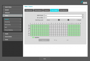
1) Turn off all the lights around a camera
– Check if the camera changes into Night Mode.
2) Check settings of a camera
– Related settings are in Day&Night tab in Camera menu under Video in Remote Setup.
– Check if B&W mode is set either On or Off and not switching.
– Check if B&W mode switching schedule is configured correctly.
– Check if Switching Level is set as desired.
I connected a lens to DC-B3303X camera, but it didn’t work. what’s the reason?
For P-IRIS lenses, since the method of operation differs from each product, it has to use the tested P-IRIS lens with the camera.
For DC-IRIS lenses, all the lenses are compatible.
The list of recommended P-IRIS lens are as follow.
– DC-B1203X : DC-IRIS lenses support only.
– DC-B3303X :
- M13VP288IR
- M13VP850IR
– DC-B1303 :
- EVETAR M117VP451016
- RICOM HV03610P
Can I use this camera for both license plate recognition and for surveillance purpose?
It cannot use for both purposes simultaneously.
Each good image quality for ANPR and for surveillance is defined differently as below, so we don’t recommend to use the camera for both purposes.
Please refer to the info below that explains why it’s hard to control the image for surveillance via ANPR IP Camera.
“Good quality” image in general video surveillance.
– Wide dynamic range
– deep depth of field
– crisp image detail
– good color saturation
– anti-flickering
– minimal motion blur
– low noise
and hundreds of other criteria.
“Good quality” image in ANPR application.
– best exposure.
– tighter iris control if possible to achieve deeper depth of field.
– shortest shutter speed to minimize the motion blur.
– black and White for better license plate capture : even though there are enough ambient lights and even though you sacrifice the color information.
– gain control to minimize the noise
There are three ways to playback recorded data in a SD card, which are listed below.
1) Access directly to the camera with the SD card through IDIS Web.
2) Register the camera with the SD card to IDIS Center and access the camera.
3) Put the SD card into a PC and run IDIS Center for iHDP to playback.
Please be aware that NVRs cannot playback recorded data in SD cards of a camera.
DC-S3583HRX and DC-S3883HRX are new speed dome camera models. These speed dome cameras take more PoE power consumption than the existing speed dome camera models.
Power consumption of the popular speed dome models DC-S1263 and DC-S1283 series ranges from 10.6W to 24.3W(Heater on). However, DC-S3583HRX and DC-S3883HRX takes maximum 68.6W with heaters and IR LEDs on.
So common PoE switches with IEEE 802.3af or IEEE 802.3at cannot provide enough power for the cameras.
Please consider using the power adaptor provided in the package of the cameras or PoE injectors capable of satisfying power consumption of the cameras.
IDIS Solution Suite has a utility to export log and setup files.
The path below is to get to the utility, Problem Reporter.
– File Start > Program > IDIS Solution Suite > Utility > Problem Reporter
Set a duration of time when a problem is thought to be occurred.
Click “Okay” to save logs and setup files in a Zip file with a name like “crashdump_20170613_103808”

Or you can even set the utility to extract the files periodically for a better maintenance
Once you get a file from Problem Reporter, please report an issue to distributor from which you bought IDIS products or IDIS Technical Support team (techsupport@idisglobal.com).
The video codecs IDIS Solution Suite supports are listed below
– H.264
– H.265
– MPEG4
– MJPEG (Data per MJPEG image is relatively huge and likely to cause fps dropping, broken images, or slow decoding depending on PC specification at an IDIS Solution Suite Client end.)
– MxPEG (Mobotix cameras exclusive)
Here are simple steps to change licensing method to offline from online.
– Go to Start > IDIS Solution Suite > License Tool.
– Run License Tool.
– Click Update as the image below shows.

– Select “OFFLINE” and proceed the rest of the steps as you authenticate the license via online licensing method.

A license for IDIS Solution Suite is activated via either offline or online method.
Please have a look at the attachment for further steps.
- Quick Zoom
- Ctrl + L-Button Drag Rectangle (on Original Image) : Dynamic Zoom
- Ctrl + L-Button Drag : Panning Zoom-In Image
- Ctrl + M-Button Down : Reset (Original Image)
- Ctrl + Wheel Scroll : Zoom-In / Out (Step)
- Quick Dewarp
- Ctrl + L-Button Drag Rectangle (on Original Image) : Dynamic PT(Fov.)
- Ctrl + M-Button Down : Reset (Original Image)
- Ctrl + Wheel Scroll : Fov-In / Out (Step)
- Ctrl + R-Button Drag (Up<->Down) : Fov-In / Out
- Quick PTZ (IDIS Camera Rubber Band)
- Ctrl + L-Button Drag : Rubber Band
- Ctrl + R-Button Drag : Zoom-In / Out
- Ctrl + Wheel Scroll : Zoom-In / Out (Step)
- Ctrl + Shift + Click : Sling Shot
Quick Control is available in v4.2.0 or higher version.
With iHDP feature, it’s possible to playback recorded data in a HDD that had been used in a NVR.
Please refer to the attachment.
SQLite has been used in ISS and the latest SQLite version compatible with ISS is 3.7.7.1.
ISS has DB files instead of DBMS files. So, ISS DB cannot be directly accessed by SQL commands and GDK, an IDIS Open Source Software, should be used to access the ISS DB.
IDIS Solution Suite supports load balancing with more than one streaming services.
Devices are evenly allocated to streaming services running in load balancing mode, and once one streaming service is offline, the other service takes all the devices from the old service.
Please refer to the attachment to find out how to configure load balancing.
Refer to the attachment for how to set up user alarm-in in IDIS Solution Suite
The ANPR Server Specification is determined by the following procedure.
- First, check which country your customer site is located in, and check the number of lanes required for license plate recognition.
- Check the required score for it in the table below.
- Check the appropriate CPU at cpubenchmark.net
- Use 16GB or a higher memory card.

For example,
Assume that you are performing license plate recognition for three lanes in Europe, The required CPU score is 10710.
Visit the site below to find the cpu for the 10710. Intel Core i7-4790K or so.
https://www.cpubenchmark.net/high_end_cpus.html

The recommended server specification is as follows.
CPU : Intel Core i7-4790K or higher
RAM : 16GB RAM , But, if the number of ANPR engine is more than 2, 32GB RAM is recommended.

To connect to the ISS Expert, uPnP setting in the NVR and manual Port Forwarding to the router are required.
However, if you set only those settings, ISS(IDIS Solution Suite) Expert will give a private IP address of the NVR to ISS client over WAN network, and you will not be able to connect the NVR with the private IP address.
In this case, FEN service is the solution for the problem.
Register a NVR to FEN Server, FEN server will pass the both of IP addresses of NVR such as public and private to the client, it will make the client access the NVR correctly.
Then the Network configuration diagram looks like this.

TR series can connect maximum 10 RTSP sessions. This is the same for TR-22xx and TR-42xx series. The sum of RTSP and live monitoring (watch) channels for TR series is maximum 10. The network transmission performance of TR-2204 is as follows mentioned in our global web site.
– 30ips @ Full HD per channel, shared with recording.
That is, TR-2204 can multiple RTSP channels more than 4, but, the transmission performance depends on the number of recording operation channels as well as the number of RTSP and watch channels.
But, TR-4208(R) and TR-4216(R) can support up to 120 ips@Full HD regardless of recording operation with multiple RTSP channels.
So, we recommend to use TR-42xx TVR if the RTSP stream performance should be stable regardless of recording operation.
Combinations of blinking status of Panic LED and Alarm LED on the front panel of NVRs indicates booting sequences.
To secure maximum performance of a camera connected to a DirectIP NVR, total number of cameras depends on what resolution a camera is registered to a NVR. The higher resolution camera is, the more camera slots are consumed per camera.
For easier and simpler designing cameras and NVRs, please refer to the table attached below.
Available number of cameras on Recorder
In the case of NVRs with firmware version V5.4.0 or higher, bitrate allocation is used, as a result of which the above table no longer applies.
Cameras and firmware versions supporting Face detection feature
• DC-B1203X – v1.3.0 or higher
• DC-S1283(W, H, F, X) – v1.1.0 or higher
• DC-D2233WHX, DC-T1233WHX – v1.0.0 or higher
• DC-S1283WRX – v1.0.0 or higher
The most likely reason is that somebody opened up IR LED part and fiddled the Zoom lens before. Then the actual location of step motor in zoom lens and where the software thinks the step motor is are different, and the difference make one push malfunction.
To reset the Zoom lens,
1) Press “Near” button on controller in PTZ mode on a NVR screen so that the Zoom lens can get as wide as it can get.
2) Press One Push, then it will find a right focus.
Please check if IR cut filter work.
On IR cut filter switching, you will be able to hear a clicking sound from a camera.
There are two ways to hear the sound of IR cut filter switching, one is to reboot a camera and the other is to switch the filter manually on a setup page of a camera.
As a camera boots up, it switches IR cut filter and you can hear a clicking sound.
Or, go to Remote Setup page of a camera and change IR Cut Filter option to “Daytime Mode” so that the camera can switch the filter manually.

If you do not hear a clicking sound from a camera when you expect to hear the sound, it would be likely to be a hardware issue, please contact the distributor from who you bought the camera or IDIS Technical Support team.
MAT(Motion Adaptive Transmission) is available in DirectIP mode.
Here is a list of IDIS cameras supporting MAT.
Dome Type
DC-D3233X: v1.2.0 or higher
DC-D3233WRX: v1.2.0 or higher
DC-D3233RX: v1.2.0 or higher
DC-D3233HRX: v1.2.0 or higher
DC-D3212X: v1.2.0 or higher
DC-D3212RX: v1.2.0 or higher
Bullet Type
DC-T3533HRX: v1.1.0 or higher
DC-T3243HRX: v1.2.0 or higher
DC-T3233HRX: v1.2.0 or higher
DC-T1833WHR: v1.2.0 or higher
DC-E3212WRX: v1.2.0 or higher
Box Type
DC-B3303X: v1.2.1 or higher
DC-B1803: v1.5.1 or higher
Other cameras with H.264 codec do not support MAT feature.
To make 3rd party cameras to be compatible with our products, we need to go through the steps listed below.
We need below information with your request.
(1) Model names and firmware version of 3rd party cameras to be tested with our products.
(2) Which IDIS product needs to be compatible to the 3rd party cameras.
(3. Expected business opportunity from that 3rd party camera integration.
(4) Due date for 3rd party cameras to be integrated with IDIS products.
Our sales department decides whether we proceed the integration or not.
As decided to to proceed, we will provide IDIS 3rd Party Test Tool to check if the current operations of 3rd party cameras to our product. Please run the tool and send us the result. To get IDIS 3rd Party Test Tool, please contact IDIS Technical support team.
Finally, send us at least two of the 3rd party camera for us to integrate and test the cameras.
IDIS Cameras support Onvif profile S.
You can find Onvif profile S specification from the below link.
https://www.onvif.org/profiles/profile-s/
If you need Declaration of Conformance on IDIS cameras for Onvif compatibility, please visit www.onvif.org and go to Conformant Products.
By creating a user’s custom name (FEN name) simply from a DirectIP NVR, its device info and network parameters (including Device name, MAC address, IP address, port info, NAT type, product info etc.) are automatically registered in the DirectIP FEN server running in the cloud. The user is able to access the site remotely using this custom name instead of an IP address, as the FEN server keeps hold of the local device’s connection on the network even in a DHCP environment with dynamic changing IP.
FEN service uses UDP hole punching for NAT traversal to gather address information of two ends, a NVR and a remote client, and NAT type in a site where a NVR is or a remote client is should support UDP communication.
[NAT types supporting UDP communication]
– Open internet
– Cone types (Full cone, Restricted cone, Port restricted cone)
[NAT types not supporting UDP communication]
– UDP blocked
– Symmetric
– Symmetric UDP firewall
Resolution:
The width of an image should be 512 or higher. For example, images with 360×240 resolution won’t be properly analyzed by the VA box and it will occur many false alarms.
– Images per second:
10 or higher ips are required.
– Protocol
DirectIP protocol only
– Codec
H.264 is supported. H.265 is also supported but the firmware version of DV-1104 should be 1.1.0 or higher. To upgrade to v1.1.0, Bios upgrade is mandatory.
Software for BIOS is downloadable along with v1.1.0 firmware.
DirectIP NVR’s
– DR-2300 series: v3.0.0 or higher
– DR-4300 series: v3.1.0 or higher
– DR-6300 series: v3.1.0 or higher
– DR-8300 series: v3.1.0 or higher
Software
– IDIS Center: V4.1.0
– IDIS Solution Suite will support DV-1104 in a future version.
Up to 4 NVRs can be registered to one DD-1116.
One NVR can be registered to multiple DD-1116. In DirectIP mode, a NVR is able to interwork with up to three units of DD-1116, but in IDIS protocol mode, a NVR can only be linked to one DD-1116.
DD-1116 normally tries synchronizing in every hour but executes time synchronization when it is one of the cases as below.
– A registered NVR is disconnected and back online.
– Time zone in DD-1116 is changed.
* When multiple NVRs are registered to a DD-1116, the decoder synchronize its time based on the time of the NVR which has been registered first.
For the cameras, DC-F1211A, DC-F1211, DC-F1111, DC-E1112WR en DC-E1212WR, the time setting will be changed randomly when the cameras reboot because their RTC(Real Time Clock) do not have batteries. For this reason, “Time Sync“ setting is necessary to automatic synchronize the time after reboot.
On DirectIP mode, the cameras do synchronize the time automatically without “Time Sync” setting because DirectIP protocol is auto-configuration oriented mode, but for the cameras running on IDIS protocol mode, the cameras do not time-synchronization unless a user manually configure the time on the menu, “Time Sync. This configuration can be set on remote setup of a camera.

Identifiers, numbers in square brackets in the picture below. are only available in IDIS Solution Suite Video Wall Agent and used for an IDIS Network Keyboard to select a device to control. The identifiers can increase as many as the number of devices that ISS Administration service can have registered because there is no limitation on the number of identifier.

FYI, Identifiers appears only in Video Wall Agent, not in IDIS Center or IDIS Solution Suite Client, and one IDIS Solution Suite Administration service can register 1024 devices.
Case 1. When there’s a software distributed by Apple running in a PC.
Auto Scan of IDIS Solution Suite uses mDNSResponder service distributed by Apple.
Software made by Apple also uses mDNSResponder. So, sometimes the Apple software conflict with Auto Scan of IDIS Solution Suite and IDIS Solution Suite cannot scan cameras.
Please delete Apple software if it is installed in a PC where IDIS Solution Suite is installed for better device scanning. Or, keep a PC or PCs to be utilized only for IDIS Solution Suite.
We provide you with a temporary password that you can login your IDIS Solution Suite to reset the password.. Before giving you a temporary password, you must send us the Secret Key of your IDIS Solution Suite first.
The steps to get Secret Key are as below.
1) Run Secret Key in Utility of IDIS Solution Suite.

2) Go to the folder path where IDIS Solution Suite is installed and access to “profile” folder.

3) Check if there is “Admin_Configuration.db” file.
4) Send the file to Techsupport@idisglobal.com.
5) As soon as we get the db file, we will provide you with a temporary password.
SD Memory capacity, basic format type and transmission speed are variable depending on SD Interface specification. IDIS IP Cameras support the SD memory interfaces listed below.
SD card
- Memory storage: 128MB ~ 2GB
- Format type: FAT16
- able to use on all devices support SD, SDHC and SDXC
SDHC card
- Memory storage: 2GB~32GB
- Format type: FAT32
- able to use on devices support SDHC and SDXC (should check logo on device for compatibility)
SDXC card
- Memory storage: 64GB ~ 2TB
- Format type: exFAT
- able to use on divices support SDXC (should check logo on device for compatibility
0: Striping without mirroring or parity
1 + 0: Striped set from a series of mirrored drives
5: Block-level striping with distributed parity
Please refer to the http://en.wikipedia.org/wiki/RAID site for detail information.
1. Recommended SFP module
– Finisar, FTLF1318P3BTL, SFP 1.25G LX / Single Mode 1310nm 10km LC with DDM
– Finisar, FTLF8519P3BNL, SFP 2.125G SX / Multi Mode 850nm 500m LC with DDM
2. Compatible SFP module
– Fottu, APS31123CDL20, SFP 1.25G LX / Single Mode 1310nm 20km LC with DDM
– Fottu, APS85123CDL05, SFP 1.25G SX / Multi Mode 850nm 550m LC with DDM
– Fottu, APSB35123CDL20, SFP 1.25G LX / Single Mode 1310nm (Tx) 20km LC with DDM Bi-Di Transceiver
– Fottu, APSB53123CDL20, SFP 1.25G LX / Single Mode 1550nm (Tx) 20km LC with DDM Bi-Di Transceiver
Of course, you can use existing switching hub, But, most non-DirectIP switching hub can’t support the specific features like DirectIP hub.
DirectIP hub supports the following features.
– PoE functionality which is designed to be able to connect both IEEE 802.3af and IEEE 802.3at PD devices though all ports can’t connect IEEE 802.3at PD devices.
– Power on/off control for each camera
– Connection notification for each camera
Therefore, if non-DirectIP switching hubs are used in conjunction with DirectIP devices, some benefits of DirectIP will diminish
Multiple recording defines the stream of recording preset which can be done from Recording schedule setting > Action setting. This feature only work with IDIS cameras.

In ISS, fisheye camera is treated the same as other camera, so it only consumes 1 channel
Other failover services (Fed, Mon, VW) status can be checked from Status menu of ISS Setup.

Load balancing only work when there are more than 2 streaming services are available.
It can create a clip-copy up to 64GB with multiple files, 4GB per file.
ISS System will stop working immediately, all services will be decommissioned. ISS Client will be logged out from ISS System. You need to restart the server after plugging back the wibu key.
- 1ch license for 1 IP camera
-
1ch license for 1 1ch IP video encoder
-
1~4ch licenses for one 4ch IP video encoder, depending on how many analog cameras are using the service[1]
-
1~16ch licenses for 1 4/8/16ch IP video encoder, depending on how many analog cameras are using the service
[1] Note that this is different from Recording ch license
- 1ch license for 1 IP camera
-
1ch license for 1 1ch IP video encoder
-
4ch licenses for 1 4ch IP video encoder, regardless of how many analog cameras are using the service
-
1ch license for 1/4/8/16ch DVR/NVR
- 1ch license for 1 IP camera
-
1ch license for 1 1ch IP video encoder
-
4ch Recording licenses for one 4ch IP video encoder, regardless of how many analog cameras are connected or enabled
-
since ISS systems do not record IP video streams from ISS compatible DVRs/NVRs, DVRs/NVRs do not use any Recording license.
Depending on the type of the license, you need to provide it to the corresponding server running its corresponding service[1]. For example, Recording ch or (Live) Streaming ch/server licenses have to be provided to the server running ISS Admin service. for Backup ch license, you provide it to each Backup server.
There are 3 different groups of licenses available for ISS v1.7.0.
-
Admin group
-
Recording ch license
-
(Live) Streaming ch license
-
(Live) Streaming server license
-
-
Backup group
-
Backup ch license
-
-
Federation group
-
Federation[1] ch license
-
[1] Typically, you will be plugging the wibu key license to the server running the corresponding service.
Wibu key is a USB license key that comes with ISS. You always need to have the wibu key plugged in the server running its corresponding service(s) at all time, or else, ISS System will stop working immediately.
Yes, but the network bandwidth and network delay overhead on the VPN may become a problem. It is advised to isolate IP video stream traffic within one subnet as much as possible, and limit VPN access to ISS client software for casual use only.
It is strongly recommended that you use LAN environment with Gigabit network for all your ISS system. If you use 100Mbps network, you can only have a handful number of IP cameras.
For example, 2MP H.264 real time (30ips) IP video stream in can reach upto 4~12Mbps. If you are recording 10 of them, and trying to do live monitoring, 100Mbps would be not be enough bandwidth.
Please refer to the manual for the specifications. The general rule of thumb is
● (Live) Streaming service uses a lot of bandwidth and CPU resources
● Video Analytics service uses a lot of CPU/Memory resources
● Admin or (Event) Monitoring services are moderately resource demanding
● Recording services require high speed storages
● PCs to run ISS Client software need to have a good VGA card, and CPU to decode multiple streams of IP video streams
It really depends on your budget. ISS System is very flexible in terms of where to install different services. Ideally, you may want to have one server run only one service. Typically, you will run Admin/(Event) Monitoring services on one server, and Recording, (Live) Streaming and VA services on three separate servers respectively.
But if your system is 32ch max, you may run all the services: Admin, Monitoring, Recording, Streaming on one server, and VA services on another server. VA service takes a lot of CPU resources[1]. If you are installing multiple services on one PC server, such as (Live) Streaming service and Recording service on the same PC server, you need to assign different (RTP) incoming port ranges for them. Refer to Incoming port range in the glossaries.
[1] 4 core CPU can handle upto 8ch in VA service
ISS Admin service uses TCP 11001 port. If the service is behind a NAT router, you need to port forward TCP 11001 on the router, so that ISS Client and other services can connect to it.
You can configure this port number on the server running the service using ISS Service Manager.
All ISS client software will stop working.
(Event) Monitoring, (Live) Streaming, and VA services will stop working. Backup service will stop working. Federation services will not be able to work with the ISS System with its Admin service crashed.
However, Recording service will continue to work, but it will be able to record Event related IP video streams only for the IP devices registered to itself only. It is because, for cross Recording service boundary event associated recording, IP camera events are collected by (Event) Monitoring service and then routed through Admin service to the other Recording service. This can not be done because Admin service is crashed.
Nothing. You are creating a new ISS system. You will need to have a new ISS license, or it will be running in demo mode. You maybe able to register IP devices, but recording may not work. Because if an IP camera is registered to two different ISS Systems, Recording may not work properly with IP cameras using ISS protocol because two ISS Systems will be competing to establish a recording session with the IP camera. IP cameras using ISS protocol allow only one recording connection session. The Recording service that establishes the recording connection to the IP cameras will keep the recording session. The other Recording service will keep trying to connect to the IP cameras, and fail.
Use ISS Setup,
- Login to the Admin service with a user account that is a member of a group with proper Setup authorities like ISS service setup and ISS schedule setup
- Select Services icon to see all the registered services.
- Double click a service or use [/] edit icon to configure the selected service
Typically, you will be first adding/registering IP devices, assigning them to different services, and then configuring the services, such as setting up Storages for Recording service, configuring VA parameters, etc.
Refer to each Service section for further service related details.
I can use ISS system without any problem, but I cannot remotely setup the IP devices, what is wrong?
If you are connecting to ISS Admin service behind a NAT router using ISS Setup, IP address scope issue may arise: IP devices and ISS Admin service are running in the same subnet behind the NAT router, but ISS Setup is connecting from the outside of the NAT router. In most of this case, the registered IP addresses of the IP devices are private IP addresses, and ISS Setup won’t be able to use the private IP addresses when it is connecting from the outside of the NAT router.
You can address this issue for IP cameras/video encoders using ISS protocol and ISS compatible DVRs/NVRs by using FEN and forwarding the corresponding ports. But when you have many different IP devices, even this approach is not manageable.
-
configure all IP cameras/video encoders using ISS protocol and ISS compatible DVRs/NVRs to use FEN
-
forward the admin port for each of them
-
register them to ISS Admin using FEN names
Typically, it is advised to run ISS Setup in the same subnet where the IP devices are running for security issues.
Use ISS Setup, and you can remotely configure the following devices:
-
IP cameras/encoders using ISS protocol
-
ISS compatible DVRs/NVRs
-
ONVIF compatible IP cameras[1]
-
compatible 3rd party IP cameras
You can upgrade the firmware of the following devices:
-
IP cameras/encoders using ISS protocol
-
ISS compatible DVRs/NVRs
[1] Only supporting the setup of the ONVIF compatible parameters exposed by the ONVIF devices.
When you install ISS services[1] on one or more servers, ISS Setup wizard will ask for the connection information of the Admin service during installation. Using this information, each service will report itself to its Admin service. An admin user will have to register these services to be included in the ISS System.
Use ISS Setup to do this. Launch ISS Setup, and login to the Admin service. Select Services icon and use + icon to register these services.
[1] except ISS Federation service
It is recommended run the service on a dedicated server if possible. ISS Admin service does not use as much computing resources as other services. Typically you will be running ISS Admin service and ISS (Event) Monitoring service on one server.
Please refer to the manual for the recommended server specifications.
When you login to an ISS system with ISS Client, you are logging into ISS Admin service, and then your ISS Client software is granted access to different IP devices, or services. ISS Client downloads information about where to find, how to connect to different devices or services using the directory of the Admin service.
ISS Admin service is a very crucial part of ISS System. If the Admin service is down, all ISS Clients will lose its connection immediately. Recording service will continue to recording IP video streams, but only for the IP video streams registered to itself because Recording service can not access Admin service that mediates Events from Monitoring service.
[1] except ISS Federation service- License authentication
- ISS Admin service authenticates licenses: Recording ch license, (Live) Streaming server/ch license.
- check current license information using ISS Service Manager on the server running the Admin service or use WibuKey Tester program on each server.
- add License certificate using ISS Service Manager on the server running the Admin service.
- Directory service of these services/devices/users,
for example- connection information to services, like External IP address/port information
- login information to the registered IP devices
- Management service of services/devices/users
- registration of services/devices/users
- service database management (backup/import)
- configuration of services,
for example,- storage setting/preparation of Recording services
- recording schedule of IP cameras
- event handling,
- event act schedule, and target user
- when to send out an email notification upon a specific event
- configure Live Popup for a specific event
- updating firmware of devices
- set up users and groups
- create/manage users and groups
- grant different levels of access privileges to different user groups
- grant access to certain IP cameras for a specific user group
- create layout, sequence, map, etc
In an ISS System, you work with many IP devices, and then a group of ISS services that provide many different features and functions. You will use ISS Client to use ISS System.
All of these services are configured using ISS Setup after logging into the ISS Admin service. Typically, you would want to limit which user groups can access these configurations using ISS Setup to change the recording schedule or event schedules.
IP cameras/video encoders using ISS protocol and ISS compatible DVRs are supported in ISS Systems. Also, ONVIF and 3rd party cameras are supported by ISS Admin service.
You can have only one ISS Admin service in one ISS System. No separate per channel License is required for ISS Admin service as long as you have an ISS Recording License.
Federation service: 11000
Admin service: 11001
Recording service: 11002
Streaming service: 11003
Monitoring service: 11004
Backup service: 11005
Video Wall service: 11006
Video Analytic service: 11007
Upgrade service: 10011
Video Wall agent service: 12000
Please refer to the How to upgrade firmware of NVR & Camera document.
Please refer to the following site and user guide.
Site: https://partner.idisglobal.com/design_tool/storage_calculator2.php
You can estimate the HDD storage capacity and network bandwidth by adjusting the stream parameters of each camera after selecting the NVR and camera.
Please download the guide document for our recording storage and network bandwidth estimator.
DirectIP NVR keeps two copies of FW and NVR setup(configuration) images on its NAND memory. Usually its first copy is used for normal operation.
Once in a while NAND Flash Memory may fail, causing the unit to fail to boot up properly to load the linux/NVR apps. When a DirectIP NVR detects 20 consecutive booting failures, it switches its active partition to the second copy to load the FW/setup properly. (It takes about 45sec for a full booting for DR-4/6100, DR-4/6200 series, so 20 rebooting will take about 15 min or so)
First try pin hole reset and if the unit still continues to reboot, wait about 15 min or so.
You can get the latest firmware from https://www.idisglobal.solutions/downloads/.
Please ask to techsupport@idisglobal.com if the release note of firmware is needed.
All NVR models that has an eSATA port are compatible with DA-ES1104.
The HDD compatibility information is not opened to the public online site.
Please ask to support@bnl.idisglobal.com with your NVR model name if you need the HDD compatibility for your NVR.
DR-4200 and DR-6200 series NVRs support the RAID 1 for redundant data protection. In addition, DA-ES1104 (IDIS eSATA Storage) can be connected to the NVR for extending the recording storage capability.
The NVR access can be protected by various authority levels; the user can add various user levels, and change them different accessing authorities. 256 users and 64 groups can be registered with various authority levels.
Please refer to manuals at Download Center https://www.idisglobal.solutions/downloads/
NVR DR-2/4/6000 series manual: Part 3 – Configuration > User
On the NVR, go to Settings > System > User

Go to Settings > Network > General

Please refer to manuals at Download Center https://www.idisglobal.solutions/downloads/
NVR DR-2/4/6000 series manual: Part 3 – Configuration > Stream
Go to Settings > Stream

The Bitrate varies denpedning on ips and resolution.
Please refer to manuals at Download Center of https://www.idisglobal.solutions/downloads/
NVR DR-2/4/600 series manual: Part 3 – Configuration > FEN
The content for FEN configuration in any IDIS NVR manual is applied for all the IDIS NVR series.

Go to Camera Registration > Scan > Third Party Scan


No. Currently, eSATA ports in NVR do not support hot swapping. So, you should connect eSATA storage to NVR before NVR is powered up. Otherwise, NVR does not recognize eSATA storage. On the other hand, if eSATA storage is swapped out while NVR is working, NVR can detect that situation and record data to another HDD.
Yes. NVR can retrieve and display the recoded audio/video data in HDD carried from another NVR.
However, NVR classifies another NVR’s HDD to ‘other HDD’ type and does not support data recording until the HDD is formatted. That is, if you want to record data to the HDD carried from another NVR, you should back up data in HDD to alternative storage device if needed, then format the HDD.
With regard to data protocols, NVR basically supports Epson, VistaATM, XApCom232, XApComIP protocols. Also, at generic text mode, user can set the transaction start/end text and line delimiter by user defined characters. You can select the hardware port and protocols on the NVR’s setup menu. For more detail configuration, please refer to the ‘Text-In’ configuration in each NVR’s manual.
Yes. Our NVRs support the Axis, Panasonic, and OnVIF network protocols for other brand’s network cameras. So if your camera has one of the protocols mentioned above, it can be used with our NVRs though the performance is not as good as the DirectIP cameras. Of course, our non-DirectIP network cameras can connect with our NVRs.
Yes. you can use conventional analog cameras with the NVR by adding network video encoders.
The network video encoder such as DE-1101 converts an analog video signal to a network video signal, and supports the DirectIP protocol.
If you use the network video encoder supporting DirectIP protocol, analog cameras can communicate with NVR by DirectIP protocol.
Currently, G.711 or G.726 audio codec standard technology has been applied in our NVR. Please refer to the A&E specification for audio codec information applied in each NVR product.
A network throughput on the NVR means local and remote multimedia data transmission rate on the network port in the NVR. For example, if maximum network throughput for local multimedia data recording and monitoring are 200Mbps and 50Mbps, respectively, and maximum network throughput for remote multimedia data transmission is 10Mbps, then maximum network throughput on the NVR is 260Mbps, which is calculated as the sum of local and remote multimedia data throughput. Using a network throughput, total number of IP cameras connected at a NVR can be determined for real time video monitoring and recording. That is, a network throughput is an important information to design and construct the NVR based network surveillance system.
Most NVRs have RJ45 female connectors on the back. You need to connect UTP cable’s RJ45 male connector to NVR’s RJ45 female connector directly. Also, you connect the cable correctly according to the WAN or LAN. For WAN, you should connect the UTP cable to the public area network port. While for LAN, you should connect the UTP cable to the local or private area network port. Mostly, CAT-5 UTP cable is used for connecting IP cameras, and CAT-5e or more higher level UTP cable is used for connecting network switching hub.
There are two types of NVRs: Standalone NVRs and PC-based NVRs. The Standalone NVRs are mostly built on Linux OS (Operating System) based system designed for embedded processors, while the PC-based NVRs are mainly MS Windows OS based system designed for PC platforms with dedicated boards for video surveillance
* Benefits of Standalone NVR
– Usually less expensive
– Takes less physical space (easy to hide on safe place)
– Safer from malwares and viruses
– Quiet in operation
– Lower power consumption
* Benefits of a PC-based NVR
– Gives better features such as video analysis, high-quality user interface, etc.
– Ability to have thousands of user accounts
– More expandable hardware and software components
– Easily maintain, change or upgrade hardware and software components
Usually, the NVRs support multi-channel video display, flexible recording schedule with different video profile with playback capability, a user friendly GUI, intelligent event detection and notification, remote monitoring and control, and PTZ camera control, etc.
There is a similar, but different network video recorders called Network Storage Recorders(NSRs). Typically, NSRs do not have video output, and all the operations are done over the IP network. So you need to use a PC to access the live or recorded video.
SMART(Self Monitoring Analysis and Reporting Technology) is a feature provided by HDD. It monitors possible conditions that the HDD has been exposed to, or status for HDD errors.
Your DVR can be configured to set the SMART information check schedule and condition. It can send alarm out or notification on SMART error.
If you see SMART error messages, it may be a good idea to change the HDD. Because it means your HDD could be damaged.
IDIS is providing various application to support each type of mobile phone. There are mobile app for iphone, android and window phone. Apps can be found by “idis mobile” as searching string. IDIS Mobile supports many features of live, play, alarm control and etc.

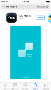
1) From DirectIP NVR
In Setup > Camera > Upgrade >, you can upgrade cameras directly from NVR. Firmware files should be stored in USB memory stick which has been put into the NVR.
2) From IDIS Discovery
To upgrade the camera from IDIS Discovery, both PC and Camera must be in the same subnet. Verify IP address first before trying to upgrade. The menu for upgrade can be found from the Management in top menu bar.
In case of WDR camera,
There is a condition to output the analog signal. CVBS analog video signal might not be generated from the camera. It’s limitation of SoC chip on WDR camera.
If 4th stream is not set (only 3 streams is operating), CVBS will perform well. In DirectIP NVR, if the custom field for recording is not set, CVBS will be outputted.
VLC player is one of the most popular player.(http://www.videolan.org/)
The command line for playing remote live video via RTSP is below
rtsp://ID:Password@IPaddress:RTSP port number/trackID=‘channel number
Please refer the capture in below for example.

850nm Infrared-ray is exposed from the IR-LED. In general, humanity can see wavelength up to 780nm (visible light : 380nm ~ 780nm)
DirectIP NVRs can set and use the each DirectIP camera’s alarm in/out ports as well as NVR’s alarm in/out ports.
For using alarm input device connected in DirectIP, you should select [Setup]-[Event]-[Alarm-In] menu sequentially. Then you can select the alarm input device connected in DirectIP as event signal channel.
For using alarm output device connected in DirectIP, you should select [Setup]-[Device]-[Alarm-Out] menu sequentially, Then you can select the alarm output device connected in DirectIP as alarm output channel.
Using the above setup configuration, you can use external alarm devices directly wired to the Camera input which will be seen by the system as if it were connected to the NVR directly.
DirectIP cameras can be configured by IDIS Discovery software and DirectIP NVRs. our INIT software help you find and configure your camera with fast and easy. Also if DirectIP cameras are connected to DirectIP NVRs, you can easily configure multiple DirectIP cameras on NVR’s setup menu. If you set multiple camera configurations on NVR, all changed parameters will be passed to each DirectIP camera immediately.
No. DirectIP cameras have no OSD menu. So, you should configure the DirectIP using our NVR, IDIS Solution Suite, IDIS Center, or IDIS Discovery software.
Spot output ports are broken into two types – RCA and terminal block. If you want to use spot output, you should check spot output port type of your camera.
Spot output on DC-X1XXX series camera works until the camera is registered to a DirectIP NVR.
If you connect DirectIP cameras to non-DirectIP NVR or VMS, you should change DirectIP camera’s protocol to ONVIF protocol using our INIT (Integrated Network Installation Tool) software. If the cameras are rebooted after the protocol is changed, DirectIP camera will operate an ONVIF camera.
It’s difficult to get a same level of performance with 3rd party cameras. Generally, with regard to transmitting video stream to DirectIP NVRs, 3rd party cameras have lower performance than DirectIP cameras. Because DirectIP protocol has specific multiple stream channels and their video profile and frame rate adjustment technology to satisfy optimal performance of video data transmission for live monitoring, recording, playing, and remote transmitting. So, if you connect 3rd party cameras with our NVRs, the benifits of DirectIP protocols are disappeared.
| Code | Impact Energy | Test |
| 00 | Non-protected | |
| 01 | 0.15 joules | Resistant against an impact from an object of 200 grams thrown from a distance of 7.5 cm |
| 02 | 0.20 joules | Resistant against an impact from an object of 200 grams thrown from a distance of 10 cm |
| 03 | 0.35 joules | Resistant against an impact from an object of 200 grams thrown from a distance of 17.5 cm |
| 04 | 0.50 joules | Resistant against an impact from an object of 200 grams thrown from a distance of 25 cm |
| 05 | 0.70 joules | Resistant against an impact from an object of 200 grams thrown from a distance of 35 cm |
| 06 | 1.00 joule | Resistant against an impact from an object of 500 grams thrown from a distance of 20 cm |
| 07 | 2.00 joules | Resistant against an impact from an object of 500 grams thrown from a distance of 40 cm |
| 08 | 5.00 joules | Resistant against an impact from an object of 1.7 kg thrown from a distance of 29.5 cm |
| 09 | 10.00 joules | Resistant against an impact from an object of 5 kg thrown from a distance of 20 cm |
| 10 | 20.00 joules | Resistant against an impact from an object of 5 kg thrown from a distance of 40 cm |
Smart IR technology automatically adjusts IR intensity according to proximity, and eliminates object over exposure caused by strong illumination. Smart IR is useful to identify a person’s face or an object movement at night.
Surveillance cameras can be classified as indoor and outdoor models according to installation place. The main difference between two models is whether the camera is weather-proof or not. That is, outdoor camera does completely protect the inner material from weather like wind, rain, moisture, dust, snow, and humidity. Some outdoor cameras should have heater or blowers for temperature resistance. On the other hand, indoor cameras do not require weather-proof or temperature resistance except critical places which get high humidity or high/low temperature.
In addition, outdoor cameras require infrared or TDN (true day/night) technology more than indoor cameras for night vision capability.
Generally, the following conditions result in a deep DOF.
– small or narrow aperature size (large f number)
– long distance between lens and subject
– short focal length
– small image sensor size (small image format)
A shallow DOF has reverse condition of a deep DOF.
TDN (True Day/Night) technology supports night vision capability by implementing a physical ICR that is removed by a mechanical motor.
DDN (Digital Day/Night) technology allows for viewing in both day and night conditions, without the use of a ICR. As light diminishes below a certain level, DDN technology switches color image to black and white image to offer similar benefits to TDN with a lower cost. At night, the captured image depends on the lighting and infrared waves off objects.
Generally, 30 IRE is a minimum value for a detailed and acceptable image.
Most cameras represent the lux level that maximum amplitude of video signal is 30% or 50% of original amplitude.
For audio detection, the device (ex. DirectIP camera) calculates the average power of audio signal that is transmitted for specific times (6.5 seconds).
If current audio signal’s power is much higher than the power threshold of audio signal (based on the average power of audio signal), then audio detection is enabled.
That is,
- Gather audio signal for 6.5 seconds
- Calculate the average power of audio signal
- Compare current power of audio signal with the power threshold of audio signal
- Decide whether audio is detected or not.
The threshold of power level is determined by the audio sensitivity level.
* Sensitivity level 1: two times (6dB) higher than the average power of audio signal
……..
* Sensitivity level 5: 1.2 times (1.6dB) higher than the average power of audio signal
NAT help us to use one public internet IP over many network devices.
The reason that you have to check the external IP address is that it is needed to connect the NVR or camera from the internet. The client uses the external IP to reach the target.
You can check the external IP address if you visit the following sites.
ISP(Internet Service Provider) is changing periodically a IP address to use limited IP range effectively. To maintain the connectivity with the server anytime, the client has to know the IP address of the server. But it’s not easy to track the IP address which is being changed constantly. Therefore, DDNS is needed.
DDNS always track and keep the available IP address of the server. When the client inquire the information to connect the server, DDNS service respond to a request. So that the client can connect to the server correctly with the connection information.
The ordinaly alignment is called 568A and 568B. It was established by TIA(Telecomunications Industry Association)/EIA(Electronic Industries Alliance).
Cable alignment 568A and 568B are below.
| Pin | T568A Color | T568B Color | Pins on patch cord |
| 1 | white/green stripe | white/orange stripe |  |
| 2 | green solid | orange solid | |
| 3 | white/orange stripe | white/green stripe | |
| 4 | blue solid | blue solid | |
| 5 | white/blue stripe | white/blue stripe | |
| 6 | orange solid | green solid | |
| 7 | white/brown stripe | white/brown stripe | |
| 8 | brown solid | brown solid |
If the both end patch are assambled as T568B, the cable can be used for ordinary LAN cable for CAT5, CAT5e, CAT6.
In case of crossover cable, one of patch cords shall be type of T568A, another one shall be type of T568B. Nowadays most ethernet adaptors support to recognize the type of the connector between T568A and T568B.
If you are experiencing such a problem, please try IDIS Discovery 4.0.6 or higher version, to which a resolution is applied.
– Check the monitor is turned on and video input cable is connected to the NVR correctly. Also, check whether the monitor cable has no defect.
– Check the display mode of monitor is set to the input source (HDMI or VGA) correctly.
– Restart NVR and check the video is displayed on the monitor within 3 minutes. If NVR is restarted, the video resolution is adjusted automatically though video resolution between NVR and monitor is not same.
– If you have another monitor, replace the monitor and restart NVR. If the video is still not displayed on another monitor properly, please report the problem to our customer support person.
Normally, NVRs or network switching hubs are PSEs (Power Sourcing Equipments) and have no consideration about the PoE and DC power because they generates the PoE power using DC power and have no collision between PoE and DC power.
However, cameras are PDs (Powered Devices) and should select one of PoE or DC power if both powers are supplied. So, if both PoE and DC power are supplied to the camera, the camera use DC power first, and send power status message to PSE via signal lines, then PSE recognizes that the camera use DC power and stop supplying PoE power to the camera.